47937c98-a25f-408d-ab82-4ea849f27efe

WHAT ARE MEDIUM VOLTAGE SWITCHGEAR EQUIPMENT?

What is Medium Voltage?

Medium voltage generally refers to electrical voltage levels between 1 kV (1000 Volts) and 36 kV, and is used in the distribution phase before and after energy transmission. Electrical energy from power plants is produced at medium voltage, transmitted at high voltage through power transmission lines, and ensures the safe and efficient distribution of energy to residential areas, industrial facilities, and infrastructure projects at medium voltage. Unlike low voltage, medium voltage systems allow for energy transmission over longer distances with low losses; they are installed with equipment such as transformer substations, MV cables, circuit breakers, and switchgear. Additionally, in some countries, due to voltage fluctuations in medium voltage distribution systems, medium voltage materials are manufactured and used up to an insulation level of 40 kV.

What are Medium Voltage Switchgear?

Medium-voltage switchgear, which plays a critical role in the transmission and distribution of electrical energy, is used in systems ranging from 1 kV to 36 kV. These systems are firmly established in power transmission lines, industrial facilities, substations, and infrastructure projects. Medium-voltage cables, medium-voltage transformers, medium-voltage circuit breakers, medium-voltage transformers, XLPE cables, and various control and protection equipment are the cornerstones of these systems.

Medium Voltage (MV) Transformer Types (Oil-filled and Dry Type)

MV transformer types are divided into two main groups:

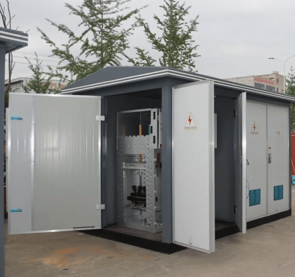
Oil-filled hermetic transformers: Generally used in outdoor environments and concrete substation systems. Cooling and insulation are provided by oil.

Dry-filled MV transformers: Suitable for indoor use. The risk of fire is low as there is no risk of explosion. They have a resin-coated winding structure.

    MV Circuit Breaker (36kV and below)

    Medium voltage circuit breakers, with their vacuum or SF6 gas construction, interrupt the line in case of short circuits and overcurrents. System safety is ensured thanks to medium voltage rooms or substations containing circuit breakers. They are mounted inside medium voltage switchgear cells.

    MV Disconnector and Grounding Disconnector

    In medium-voltage switchgear systems, disconnectors are used to physically isolate the circuit by voltage. The circuit is interrupted when there is no load and comes with a safety interlock. The grounding disconnector grounds the system after the circuit has been isolated.

    OG Surge Protector

    Surge arresters protect medium-voltage (MV) transformers, switchgear, transformers, and transmission lines against voltage surges caused by lightning and switching impulses. They are frequently preferred in 36 kV systems, both inside MV switchgear and in open areas.

    MV Digital Protection Relays

    Medium voltage digital protection relays are programmable devices that detect faults (phase-to-ground, phase-to-phase, imbalance, etc.) occurring in the lines and trigger medium voltage circuit breakers. They are compatible with SCADA and automation systems.

    OG Cable

    In medium voltage (MV) power transmission, XLPE cables are generally used in different cross-sections:

    1×50/16 XLPE cable is suitable for compact lines.
    1×95/16 XLPE cable has a high load-bearing capacity and offers high thermal resistance.
    The price of 1×120 XLPE cable increases with the cross-section.
    The price of 1×400 XLPE aluminum cable is more economical than copper due to the conductivity of aluminum.
    6.3 kV XLPE cable is used in transition voltage levels between low and medium voltage.
    36 kV XLPE cable is preferred in long-distance MV lines.
    The price of XLPE cable varies according to conductor type, shielding structure, and voltage level. XLPE cable unit price analyses are decisive in project cost planning. Cables diversified like YAXC7V-R are special ferrule-type cables for MV lines. Medium voltage cable prices are evaluated based on cross-section, length, and type.

    MV Cable Heads

    Medium voltage cable terminations ensure a secure connection of the medium voltage cable to the panel or transformer. They come in indoor and outdoor types, and are also classified as standard and plug-in types.

    MV Current and Voltage Transformer

    Medium voltage (MV) current transformers reduce the low current at high voltage to values ​​of 1 Ampere or 5 Amperes, sending signals to meter and relay systems.

    36 kV voltage transformers, on the other hand, reduce the high voltage to 100 VAC and are central to measurement and protection systems. MV voltage transformer prices are determined according to their class sensitivity and voltage level.

    OG Battery Rectifier Group

    In medium voltage (MV) systems, auxiliary voltage is required for relays, communication modules, and circuit breakers. This is provided by a battery rectifier set. 24VDC and 110VDC systems are particularly common.

    Busbars and Insulation Materials

    Copper or aluminum busbars are used for medium voltage current transformers and connection systems. Voltage cable connections in MV systems must be insulated.

    Insulating mats, insulating gloves, and insulating rods, which are included in the medium voltage equipment groups, are mandatory for occupational safety.

    Other Materials Used in Medium Voltage Applications

    Medium voltage poles vary according to the project and are offered in galvanized or reinforced concrete types. Medium voltage companies offer solutions covering material supply, field installation, and service. Medium voltage drives are frequency converters used for the efficient operation of MV motors. Medium voltage fuses are used only to interrupt the current in cases where there is no circuit breaker in the system. Fuse types differ according to current limit and magnitude.

    Medium voltage switchgear is the backbone of the system in both energy infrastructures and industrial facilities. The harmonious operation of dozens of components such as MV XLPE cable, medium voltage transformer prices, MV material prices, voltage transformers, and cable terminations determines the efficiency and safety of the system.

    For solutions suitable for your project, products that comply with the technical specifications and have quality certificates should be preferred. In MV systems, the correct material selection ensures long lifespan, low failure rate, and high energy efficiency.

    b5d50b21-186a-4006-b4dc-644300ebc523

    WHAT IS A MOBILE TRANSFORMER SUBSTATION?

    A mobile substation, as the name suggests, is a portable transformer solution used for temporary or emergency situations in the transmission and distribution of electrical energy. Typically mounted on trailers or semi-trailers, these systems are designed to ensure the continuity of energy supply thanks to their ability to be quickly commissioned.

    Mobile substations come into operation when fixed substations become unusable, preventing interruptions in the flow of energy. This provides a quick solution both during planned maintenance processes and in case of malfunctions. Furthermore, they are an indispensable solution in scenarios where energy needs must be met quickly, such as in newly established residential areas, large-scale construction sites, or disaster zones.

    Why do we need mobile transformer substations?

    Today, tolerance for power outages is quite low. Outages in both residential areas and energy-intensive facilities such as hospitals, factories, or schools can have serious consequences. In such cases, when fixed substations are insufficient or out of service, mobile substations can be quickly activated to meet temporary power needs.

    If the capacity of an existing substation in a region is insufficient, or if it needs to be upgraded to meet TEDAŞ (Turkish Electricity Distribution Company) standards, mobile substations are temporarily activated to prevent the region from being without power during this process. They also offer flexible solutions to grid needs in scenarios such as population growth, migration waves, or sudden load increases in industrial areas.

    What is the difference between mobile transformers and standard, conventional transformer substations?

    Standard fixed substations are installed in open-field configurations if high voltage is present in the system, and in concrete or prefabricated enclosures if medium voltage is present. These include building-type substations, gas-insulated GIS substations, or open-type substations. However, the installation, commissioning, and testing processes of these fixed systems can be time-consuming. Mobile substations offer temporary solutions that bridge this gap.

    For example, converting an existing substation into a modern GIS substation can take weeks or even months. Mobile substations are preferred for areas with limited power supply.

    Applications of Mobile Transformer Substations

    Mobile substations play a critical role not only in maintenance processes but also during disasters and crises. Energy infrastructure can be damaged during natural disasters such as earthquakes, floods, and storms, or during extraordinary situations like war. In such conditions, mobile substations can be deployed to meet the need for temporary and reliable energy, ensuring the uninterrupted operation of hospitals, military facilities, or critical production centers.

    In large infrastructure projects, such as dam or tunnel construction, the energy demand on site is both high and dynamic. In such locations, transmitting energy over long distances at low voltage levels of 400V is impractical; both losses increase and the cable cross-section becomes larger. Therefore, it is necessary to transmit energy at medium voltage and reduce it to low voltage at points close to the construction site. This is where mobile substations come into play.

    Furthermore, mobile substation systems are highly suitable for rapid installation and energy access in areas inaccessible to infrastructure, such as military bases or factories in mountainous regions.

    At what voltage levels are they used?

    Mobile substations can be used temporarily at 154 kV and 380 kV levels during maintenance, fault repair, or temporary commissioning processes of high-voltage lines, or when there is a fault or maintenance in open-type step-down and step-up substations. Such applications are generally geared towards the needs of transmission-level operators such as TEİAŞ (Turkish Electricity Transmission Corporation). Integrated onto GIS (Gas Insulated Switchgear) systems, they offer both a safe and compact structure. Although fewer examples exist at medium-voltage levels, they can be preferred as an alternative to building-type substations.

    Advantages of Mobile Transformer Substations

    The main advantages offered by mobile transformer systems are:

    Portability: They can be easily transported to the desired location.

    Fast commissioning: Installation and commissioning can be completed in a short time.

    Low investment cost: It can be more economical than fixed installation.

    Flexibility: It can be adapted to different scenarios for temporary and permanent needs.

    Compact structure: It takes up little space and requires minimal infrastructure.

    In today’s conditions where uninterrupted energy supply is essential, mobile transformer substations are used not only for sudden failures but also in many areas such as maintenance, infrastructure renewal, capacity development, and crisis management.

    decaf8d2-6c28-4be8-8a57-1f0f6645e32b

    MEDIUM VOLTAGE CURRENT TRANSFORMERS

    What is a medium voltage current transformer?

    Medium-voltage current transformers are one of the essential components used in electrical distribution systems to safely and accurately measure current. Since directly measuring high currents is both risky and costly, these currents must be converted to lower values ​​before measurement. This is where medium-voltage current transformers come into play.

    A current transformer reduces the high current in the primary circuit to levels that measuring instruments can operate at – typically 1 A or 5 A – and transmits it to the secondary circuit. It also isolates the measuring instruments from the high current in the primary. These transformers are connected in series with the circuit, and under normal conditions, there is no significant phase difference between the primary and secondary currents.

    Working Principle of Current Transformers

    Current transformers operate on the principle of a classic transformer. As alternating current passes through the primary winding, it creates a magnetic field. This magnetic flux is transmitted through the core to the secondary winding, induced by a voltage. This induced voltage creates a current in the secondary circuit, transmitting data to measuring devices.

    Structurally, primary windings have fewer turns and thicker conductors because they carry high currents. Secondary windings, on the other hand, are made of thinner conductors with many turns. This structure allows for the correct conversion of current and ensures insulation.

    Current Transformer Classes and Error Coefficients

    Depending on their application, current transformers are classified as measurement and protection types. Measurement transformers maintain their accuracy only up to a certain current limit, while protection transformers are manufactured to transmit accurate data even at high currents that may occur in the system. This difference is determined by the saturation characteristic of the transformer’s magnetic core.

    Current transformer class values ​​determine the measurement accuracy. For measurement transformers, classes are generally 0.1, 0.2, 0.5, 1, 3, and 5. Protection current transformers are defined by classes such as 5P or 10P. The “P” (Protection) on the label indicates the protection class, and “Fs” (Security Factor) indicates the measurement class. Transformers in the measurement class have values ​​such as Fs5 or Fs10.

    The saturation factor (n) is the ratio of the primary current to the rated current. Measurement transformers generally operate with n<5 or n<10; Magnetic saturation starts late in protective transformers. This is critical for the correct operation of protective relays, especially in situations such as short circuits.

    Considerations When Selecting a Medium Voltage Current Transformer

    When selecting a medium voltage transformer, class information alone is insufficient. Thermal and dynamic withstand values ​​must also be considered.

    Ith (thermal withstand current) indicates the transformer’s capacity to withstand short-term high currents and should generally be at least 100 times the nominal current.

    Idyn (dynamic withstand current) is typically 2.5 times the thermal withstand current.

    Furthermore, allowing current to flow through the primary terminal while the secondary terminals are open can cause a high voltage to build up in the secondary. Therefore, the secondary terminals must be short-circuited before any work is performed on the transformer.

    Types of Medium Voltage Current Transformers

    Three types of current transformers are commonly used in medium-voltage systems:

    Support Type Current Transformer

    These transformers, insulated with epoxy resin, are mounted inside medium-voltage switchgear. They are common at medium-voltage levels such as 24 kV and 36 kV.

    Toroidal Current Transformer

    These ring-shaped transformers are generally used at low levels such as 0.72 kV. They provide an output current of 1 A or 5 A. Their compact structure provides a space advantage in medium-voltage switchgear.

    LPCT (Low Power Current Transformer)

    Similar to toroidal transformers, these produce voltage at the mV level and are directly connected to protection relays via RJ45 cable. They are generally preferred in switchgear with digital relays. They have an adjustable current range between 0–1250 A. The secondary output is voltage, not current, as in classic transformers.

    Application Areas and Advantages of MV Current Transformers

    Medium voltage current transformers (MV current transformers) are generally used in substations, power distribution panels, MV switchgear, and power generation facilities. They are integrated into the system for both measurement and protection purposes. In MV systems, toroidal transformers are preferred due to their space-saving properties; they are ideal, especially in scenarios where short-circuit protection is not critical.

    Today, both domestic manufacturers and global companies offer a wide range of MV current transformers and MV voltage transformers. Selecting the correct transformer type and class according to the application directly affects the healthy and long-lasting operation of the system.

    28010d85-e2e7-46a5-9c38-76a9ab4b49b6

    DRY-TYPE TRANSFORMERS

    Transformers used in electrical transmission and distribution systems are divided into two groups based on their structural characteristics: oil-filled and dry-type. The advantages and disadvantages of these two types vary depending on their application areas. Dry-type transformers stand out in terms of safety, especially in enclosed spaces where many people are present.

    Oil-filled transformers, which contain insulating oil, may pose safety risks such as fire or explosion. However, dry-type transformers do not present such a danger. Therefore, dry-type transformers are preferred in indoor applications such as hospitals, schools, shopping malls, and similar buildings. However, dry-type transformers are more sensitive to external environmental conditions compared to oil-filled models.

    Dry Type Transformer Structure and Manufacturing Characteristics

    In dry-type transformers, the high-voltage windings are coated with epoxy resin, usually cast in a vacuum. This coating provides strong resistance to moisture, chemical effects, and electrical stresses. The low-voltage windings are insulated with epoxy resin or prepreg technology. In this type of transformer, the windings are not protected by any oil; they operate directly exposed to environmental conditions.

    Depending on the environment in which the transformer operates, it can be used in cabinets with different protection classes such as IP00 (unprotected), IP21, IP23, or IP31. This makes it possible to customize dry-type transformers according to the installation environment.

    Power Ratings and Dimensions in Dry Type Transformers

    Dry-type transformer power ratings generally start from 250 kVA and can reach up to 8 MVA in special applications. One of the most common models is the 1600 kVA and 2500 kVA dry-type transformers. However, transformers of this power rating do not fit into standard concrete substations; therefore, physical space requirements must be carefully calculated when preparing layout projects.

    In TEDAŞ (Turkish Electricity Distribution Company) projects, the maximum dry-type transformer power rating to be placed inside a building is generally limited to 1250 kVA. This limit is standardized for both safety and layout reasons.

    Cooling Methods in Dry Type Transformers

    In terms of cooling method, oil-filled transformers dissipate their heat through circulating transformer oil, while dry-type transformers are cooled by natural airflow. These methods are divided into two categories:

    AN (Air Natural): Cooling by natural airflow

    AF (Air Forced): Fan-assisted cooling

    Fans are usually located in the lower section of the transformer and are controlled by temperature sensors. Thanks to this structure, the transformer can operate safely even under an additional load of up to 40% depending on demand. However, dry-type transformers without cabinets and with an IP00 rating should only be used indoors; for outdoor applications, they must be protected by a cabinet with the appropriate IP protection rating.

    Insulation Material Temperature Classes

    Winding materials used in dry-type transformers are selected according to temperature classes that determine thermal resistance:

    Class F: Resistant to temperature increases up to 155°C.

    Class H: Can operate up to 180°C.

    In transformer technical documentation, the winding class is indicated as “F/F” or “H/H”. These classes are important technical details to consider when selecting a transformer.

    Environmental, Climate and Fire Resistance According to IEC 60076-11 Standard

    The environmental resistance of dry-type transformers is determined according to the international IEC 60076-11 standard. The most commonly used classes are summarized below:

    Environmental Class:

    E0: Can operate in clean and dry environments.

    E1: Tolerant to light pollution and low condensation.

    E2: Can operate in heavily polluted and humid environments.

    Climate Class:

    C1: Cannot operate below -5°C, but can withstand temperatures down to -25°C.

    C2: Can operate without problems down to -25°C.

    Fire Resistance Class:

    F0: Used in environments with low fire risk.

    F1: Preferred in locations requiring high fire safety.

    Most transformers are manufactured to have E2 – C2 – F1 classes. This makes them suitable for safe use even in harsh environmental conditions.

    Dry-Type Transformers of the TEDAŞ Type in Turkey

    Dry-type transformers to be transferred to public ownership in Turkey must be manufactured in accordance with the TEDAŞ-MLZ/99-031.B technical specifications. These transformers are notable for their overload resistance, lack of explosion risk, seismic resistance, and the possibility of use in enclosed cabinets.

    Why Choose a Dry Type Transformer?

    Dry-type transformers are preferred because of their low maintenance requirements, lack of explosion risk, fire safety, quieter operation, environmentally friendly structure, compact design, and space-saving features. Many manufacturers offer products in different power capacities such as 400 kVA, 630 kVA, 1600 kVA, and 2500 kVA. Dry-type transformer prices vary depending on the model’s power, insulation class, whether or not it has a protective cabinet, and the type of tap changer. Today, dry-type transformer solutions have become the preferred choice in many projects due to both their technical performance and the safety advantages they offer.

    b2491bb7-4c3b-470d-8901-50ebdc10da91

    MEDIUM VOLTAGE CELLS

    What is a Medium Voltage Modular Cell (MV Cell)?

    Medium voltage (MV) switchgear, also known as modular switchgear, is a compact and safe switchgear equipment used in power distribution systems up to 36 kV for switching, protection, and measurement operations. It is used in numerous applications, including transformer substations, industrial facilities, and step-down and step-up substations.

    These switchgear integrates many components, including MV circuit breakers, disconnectors, load disconnectors, current and voltage transformers, protection relays, busbar systems, and cable connection points. Their compact design saves space, while their modular structure facilitates system expansion. Generally maintenance-free, these structures prioritize user safety and offer ease of operation.

    MV Cell Types: Air and Gas Insulated MV Cells

    MV switchgear is classified into two main groups according to its insulation type:

    Air-insulated MV switchgear: Busbars are insulated with air. Circuit breakers and disconnectors may be located in tanks filled with SF6 gas. These types of switchgear are generally larger in volume but offer advantages in terms of maintenance.

    Gas-insulated MV switchgear (GIS): All active parts are located in a metal enclosure insulated with SF6 gas. Thanks to its compact design, it offers an ideal solution for applications with space constraints. These types of switchgear are commonly known in the industry as RMU (Ring Main Unit).

    MV switchgear contains many different elements such as busbar systems, disconnectors, grounding disconnectors, MV circuit breakers, protection relays, surge arresters, MV fuses, indicator lamps, lighting equipment, and measuring transformers. The contents may vary depending on the switchgear type and function.

    OG Cell Structure and Classifications

    MV modular switchgear is structurally classified according to different criteria:

    1. Compartment Type

    PM (Metal Compartment): Components under voltage are separated by grounded metal compartments with open access areas.

    PI (Insulating Compartment): This separation is achieved with insulating materials. Generally, they stand out due to their lower cost and lighter weight.

    1. Internal Arc Resistance (IAC Classes)

    A: Only authorized technical personnel can access.

    F: Access is possible from the front surface.

    L: Side surface access is possible.

    R: Access is possible from the rear surface.

    1. Service Continuity (LSC Classes)

    LSC-1: All components in the switchgear are in a single compartment; the entire system must be de-energized for any intervention.

    LSC-2A: Intervention on other components is possible while the busbars are energized.

    LSC-2B: Access to switching elements is possible while both the busbar and cable compartment are energized.

    OG Cell Rating Values ​​and Sizing

    Commonly used medium voltage (MV) switchgear in Turkey has a rated voltage of 36 kV, a continuous current carrying capacity of 630 A, and a short-circuit breaking capacity of 16 kA. The physical dimensions of these switchgear vary depending on the voltage they carry. In an air-insulated 36 kV switchgear, an average spacing of 36 cm should be left between the busbars for safe insulation. This calculation is based on the dielectric strength of air, which is approximately 1 kV/cm, and directly affects the physical dimensions of the switchgear.

    The superior insulation properties of SF₆ gas allow for the construction of a structure that occupies less space at the same voltage in gas-insulated switchgear. Therefore, these switchgears are frequently preferred in confined spaces.

    TEDAŞ-type medium voltage switchgear used in Turkey.

    In our country, MV switchgear is manufactured according to TEDAŞ standards based on project requirements:

    Switchgear to be used in SF6 gas systems must fully comply with TEDAŞ-MYD/95-002.B; air-insulated metal-enclosed switchgear must comply with TEDAŞ-MYD/95-007.E.

    MV switchgear can be manufactured according to different protection classes such as IP 3X, IP 4X, IP41. The most common switchgear types are:

    Load disconnect switchgear (input/output)
    Fused transformer protection switchgear
    Switchgear (input/output)
    Switchgear (input/output)
    Switchgear (transformer protection switchgear)
    Coupling switchgear
    Cable connection switchgear
    Measuring switchgear (current/voltage)

    Applications of OG Cells

    MV modular switchgear is widely used in many areas such as:

    Urban distribution centers
    Organized industrial zones
    Renewable energy power plants
    Industrial facilities
    Low and medium voltage transformer substations

    They save space and offer high personnel safety. Thanks to their compact structure, the system can be easily expanded. MV switchgear is a modular switching element that offers high safety, ease of operation, and long service life in energy distribution facilities. Properly selected MV switchgear increases facility safety and guarantees system continuity.

    28330dc2-2bdd-472e-9183-024e57bf9cfb

    OG PROTECTION RELAY

    What is a OG Protection Relay and How to Choose One?

    Medium voltage (MV) protection relays, a cornerstone of safety in electrical systems, are used to protect circuit elements in medium voltage networks against faults. Protection systems are of paramount importance, especially in the energy supply chain from generation to consumption, as a potential fault can disrupt the balance of the entire system.

    Protection relays used in medium voltage systems, thanks to their microprocessor-based structure, analyze data received from measuring transformers and send a tripping signal to circuit breakers when they detect an anomaly in the system. In this way, the fault is quickly isolated, and the rest of the system continues to operate.

    What is the function of an MV Protection Relay?

    A protection relay continuously monitors the current and voltage values ​​in the system. When conditions such as overcurrent, ground fault, voltage drop, or phase imbalance are detected, the relay evaluates the situation according to predefined set values ​​and intervenes in the circuit breaker if necessary.

    An overcurrent relay instantly detects the situation when the current in the circuit exceeds the limits and opens the circuit breaker, preventing damage to the devices in the system. Relays perform this intervention in milliseconds. These relays are equipped with different functions to protect equipment such as transformers, motors, generators, and lines.

    Considerations When Selecting an MV Protection Relay

    The selection of an MV protection relay should be based not only on the technical specifications of the system, but also on the needs of the facility, protection scenarios, and selectivity requirements.

    Selection Criteria:

    Electrical protection equipment (transformer, motor, line, etc.)
    ANSI protection function codes
    Relay communication protocol (Modbus, IEC61850, etc.)
    Fast opening/closing time
    User interface and software support
    Set value adjustment accuracy

    Protection functions are defined according to ANSI standards, and the functions each relay has are specified in its technical documentation. For example, while the MV line protection relay must have features such as directional overcurrent (67) and earth leakage protection (51N); if motor protection is to be performed, the thermal overcurrent (49) function becomes critical.

    Most Commonly Used ANSI Protection Functions

    The most commonly used ANSI codes and their corresponding meanings in medium-voltage transmission and distribution systems are listed below:

    27 Undervoltage Protection

    32 Directional Power Protection

    46 Phase Imbalance (Negative Current)

    49 Thermal Overcurrent Protection

    50 Inrush Overcurrent Protection

    50N Inrush Ground Fault Protection

    51 Time-Delayed Overcurrent Protection

    51N Timed Ground Fault Protection

    59 Overvoltage Protection

    67 Directional Overcurrent Protection

    67N Directional Ground Fault Protection

    81U Low Frequency Protection

    81O High Frequency Protection

    87T Transformer Differential Protection

    87L Line Differential Protection

    The correct relay selection should be evaluated according to these functions.

    What is an Overcurrent Protection Relay?

    In electrical installations, overcurrent protection relays play a critical role in ensuring system safety. Overcurrents can occur as a result of short circuits, sudden overloads, or various system failures. A properly configured overcurrent relay can protect electrical equipment from serious damage in these situations.

    Different models, such as motor overcurrent relays, high current relays, and time-delay relays, are chosen according to the application type. The set values ​​of these products must be programmed according to the ratios and operating characteristics of the measuring transformers in the field.

    Choosing the correct protection relay plays a critical role in medium-voltage systems, both in terms of equipment safety and the protection of field personnel. These systems, which provide quick and selective intervention in case of a fault, offer significant advantages in terms of energy continuity and equipment health.

    A medium-voltage protection relay with the correct functions and programmed with appropriate set values ​​ensures the safe operation of your system for years to come. This precaution against events such as overcurrent, ground faults, and voltage surges prevents major failures and costs in the long run.

    7d33256b-859b-49a0-8720-7173baa13958

    WHAT IS A HERMETIC TRANSFORMER (OIL-FILLED TRANSFORMER)?

    Hermetic Transformers (Oil-Type Transformers)

    Transformers, used for the safe and efficient transmission of electrical energy, are designed with different structural characteristics depending on the application area. These systems are generally divided into two main groups: oil-filled transformers and dry-type transformers. The most common and widely used solution in the field, especially suitable for outdoor applications, is the oil-filled transformer.

    Thanks to their durable structure and high efficiency, oil-filled transformers can operate for many years in harsh environmental conditions. They are also more advantageous in terms of cost compared to dry-type models. However, in these systems, the insulation and cooling mechanism is provided by transformer oil, unlike dry-type transformers. Transformer oil performs a dual function: it reduces the temperature of the windings while also providing electrical insulation.

    The Difference Between Hermetic and Oil-Filled Transformers with Expansion Tanks

    Oil-filled transformers are divided into two types according to their design: hermetic and expansion tank type. Both models have an oil cooling system, but they differ in how they handle oil expansion.

    Hermetic transformers are sealed to provide complete insulation between the interior and exterior atmosphere. The oil, filled under vacuum, circulates in a closed tank. When the oil heats up, its volume expands, and this expansion is absorbed by the corrugated wall structure of the transformer tank. Because there is no direct contact with the external environment in this type, contaminants such as moisture, dust, or liquids cannot enter the oil; this reduces the need for maintenance.

    In transformers with an expansion tank, the oil is located in an open-system expansion tank along with the tank and is in contact with the external environment. This controls the increase in oil volume caused by heating. When the heat increases, the oil expands towards this tank, and when it cools, it returns. However, because there is contact with air in this design, silica gel is used to protect against internal moisture. Silica gel retains moisture from the air, preserving the insulation quality of the oil. It needs to be replaced as its color changes.

    Internal Structure of Hermetically Sealed Oil-Type Transformers

    The basic components of an oil-filled transformer are:

    Aluminum or copper windings
    Magnetic core made of silicon steel
    Transformer oil
    Tap changer
    Hermetic tank
    Radiator or corrugated walls
    Oil temperature thermometer
    Hermetic control relay (pressure, gas, temperature gauge)
    Cable bushings and wheels
    If the transformer has an expansion tank, a Buchholz relay and expansion tank are also included.

    Transformer Winding Material: Aluminum or Copper?

    Transformer windings can be made from aluminum or copper conductors depending on the application. In Türkiye, according to TEDAŞ specifications, aluminum is generally preferred for distribution transformers up to 2500 kVA. This is because aluminum is both cheaper and lighter. However, using aluminum in high-power transformers such as 10 MVA increases the tank volume, thus raising the total cost. Therefore, as the power increases, copper windings are preferred, resulting in more compact and economical solutions.

    Oil-Type Transformer Cooling Methods

    Heat generated in transformers generally comes from two sources:

    Copper loss (loss at load)

    Core loss (loss at no load)

    To dissipate this heat, transformer oil absorbs the heat from the windings and transfers it to the external environment via radiators or corrugated walls. Cooling systems are classified as follows:

    ONAN Transformer oil + natural air cooling
    ONAF Transformer oil + fan-assisted air cooling
    OFAF Fan-assisted oil + fan-assisted air cooling
    OFWF Fan-assisted oil + water cooling
    ONAN type cooling is generally preferred in distribution transformers, while ONAF type cooling is preferred in power transformers.

    Oil-based Transformer and Insulation Oil

    Transformer oil is not just a coolant; it is also a critical component providing electrical insulation. Its properties are even more important, especially in hermetically sealed transformer systems. The oil used must have high dielectric strength, conduct heat effectively, and be free from external factors such as moisture, air, and dust. The quality of the oil should be checked through periodic oil tests and sample analyses. Otherwise, the insulation may weaken, and a short circuit may occur between the windings.

    Protection Relays in Oil-Filled Transformers

    In hermetic transformers, digital control relays are used. These relays monitor parameters such as gas release, internal pressure, and oil temperature, and when limit values ​​are exceeded, they trip the circuit breaker in the MV cell. Oil-filled transformers with expansion tanks use an analog type relay, called a Buchholz relay. It detects oil leaks, gas accumulation, or sudden fluctuations and generates a protection signal.

    Oil-filled transformer prices and application areas.

    There are many leading transformer companies and manufacturers in Türkiye in this field. Transformer prices vary according to the following factors:

    Power capacity (e.g., 400 kVA, 1000 kVA, 1600 kVA, etc.)
    Winding material (aluminum or copper)
    Cooling type (ONAN, ONAF, etc.)
    TEDAŞ (Turkish Electricity Distribution Company) or private project approval
    Protection relay type and communication feature

    Use and Maintenance of Hermetically Sealed Oil-Type Transformers

    Hermetically sealed oil-filled transformers stand out with their long lifespan and reliable construction. Thanks to their high efficiency ranging from 98% to 99%, they minimize energy losses. They generally only require periodic maintenance, significantly reducing the need for intervention during operation. In TEDAŞ-approved projects, models up to 1600 kVA are mostly used in concrete substation applications. They have a wide range of uses, from industrial facilities and organized industrial zones to housing projects, power plants, and infrastructure applications. Especially in systems operating in open areas and challenging environmental conditions, hermetically sealed oil-filled transformers offer an ideal solution with their high level of safety and low operating costs.

    36f4e734-f9b4-4a70-bf45-942bea8ea68d

    TRANSFORMER SUBSTATION: CONCRETE SUBSTATION AND PREFABRICATED SUBSTATION

    What are Transformer Substations? Basic Information about Concrete Substations, Prefabricated and Metal Structures.

    Transformer substations, which ensure the safe and controlled distribution of electrical energy in the field, consist of medium-voltage switchgear, transformers, low-voltage panels, power cables, and various auxiliary equipment. Special enclosure structures are used to protect all these systems from environmental influences. These structures are generally referred to as transformer kiosks in the industry.

    Located in residential areas, industrial zones, or energy infrastructure projects, these structures can be designed in the form of concrete kiosks, prefabricated kiosks, or metal kiosks. The interior layout is shaped according to the needs of the transformer substation. Medium-voltage switchgear, transformers, and low-voltage panels are usually placed in separate rooms. This separation is important for both safety and ease of maintenance. The contents of these structures can be expanded or simplified according to the usage scenario.

    Concrete Pavilion Usage and Structural Characteristics

    Concrete substations are among the most preferred enclosure structures for medium and low voltage systems. These substations, with their reinforced concrete exterior, are often produced as monoblock, meaning they are made of a single piece. Because the foundation and side walls are poured together, they offer advantages in terms of both structural integrity and watertightness. The substation’s floor has passages suitable for underground cable connections. This allows medium and low voltage cables to be brought directly into the substation from underneath.

    The ceiling area can be designed to relieve sudden gas pressure, especially in the event of internal arc faults. The concrete exterior surfaces are reinforced with external cladding to provide resistance to weather conditions. The roof structure is also designed to prevent rain or snow leakage. Doors are generally made of galvanized sheet metal and are mounted to offer a wide opening.

    Concrete substations produced in Turkey must be manufactured in accordance with the TEDAŞ MYD/2000-036.C technical specification. This standard; It covers many critical topics such as safety, structural integrity, ventilation, insulation, and interior design.

    Concrete Pavilion Dimensions and Usage Limits

    The dimensions of concrete substations depend on the transformer’s power and the characteristics of the installation area. This type of substation is mostly preferred in systems of 400 kVA and above. However, due to production limitations, concrete substations can generally only be manufactured up to a maximum of 7.2 meters. If a transformer building larger than this is required, prefabricated or metal substation solutions can be considered as alternatives.

    Prefabricated Transformer Substations

    Prefabricated substations are preferred in large projects due to their ease of assembly and flexible size options. Similar to concrete substations, they contain separate sections for MV and LV panels, as well as the transformer. However, these structures are delivered to the site in disassembled form and assembled on-site. Their exteriors can be painted in various colors and secured with mechanically lockable sections.

    The standard applicable to prefabricated structures used in TEDAŞ (Turkish Electricity Distribution Company) projects is the TEDAŞ MLZ/2006-52.A specification. This document defines the technical, structural, and safety criteria for prefabricated transformer substations. With an IP23 protection class, these structures offer adequate protection against external environmental conditions.

    Metal Pavilion Usage Areas and Features

    Metal substation enclosures stand out from other solutions in terms of portability and lightness. Their bodies are made of hot-dip galvanized sheet metal, and their inner and outer surfaces are generally coated with electrostatic powder paint. In medium voltage (MV) projects, the RAL 7032 color code is commonly used, but custom color options are also available. The roof is designed with insulation to reduce heat transfer.

    Metal substation enclosures can be used for transformers ranging from low-power transformers like 50 kVA to those up to 4000 kVA. They can integrate not only transformers but also additional equipment such as MV switchboards, LV switchboards, battery-rectifier groups, or generators. They can be shipped fully assembled on site or empty.

    Lighter than concrete substations, these structures can be easily transported to distant locations by road. Especially in international projects, mobile transformer substation solutions, transportable on trailers or semi-trailers, are created using metal substation kiosks. Although TEDAŞ (Turkish Electricity Distribution Company) does not have specific technical specifications for metal substations, these products are generally shaped according to project-specific technical requirements.

    When planning a transformer substation, the type of kiosk to be used should be determined according to the system’s power, installation area, and environmental conditions. Options such as concrete kiosks, prefabricated kiosks, and metal kiosks each offer advantages for different needs. In choosing the right transformer substation, attention should be paid not only to power capacity but also to technical details such as the dimensions of the kiosk, the placement of internal equipment, the ventilation system, and maintenance access. A properly designed and project-specific transformer building ensures both safe energy distribution and contributes to the longevity of the system.

    171ce9d6-ec00-4309-8c20-68cc2c2053be

    MV VOLTAGE TRANSFORMERS

    What is a medium voltage transformer?

    The safe, measurable, and controllable management of electrical energy depends not only on the transmission lines but also on the proper functioning of the entire infrastructure. One of the invisible but indispensable components of this infrastructure is the voltage transformer. Particularly used in medium-voltage (MV) systems, the MV voltage transformer plays a critical role in protection and measurement applications.

    What is a voltage transformer?

    A voltage transformer is a type of transformer that reduces the electrical voltage in high-voltage lines to a measurable and safe level, providing suitable signals for measurement and protection systems. While the primary winding is directly connected to the MV busbar or phase line, the secondary winding typically produces a standardized low voltage, such as 100 V or 110 V. This allows electricity meters, energy analyzers, and protection relays located in MV switchgear to take measurements without being exposed to high voltage.

    What is the purpose of an MV voltage transformer?

    In systems operating at medium voltage levels, direct measurement is both dangerous and technically impossible. Medium voltage transformers reduce high voltage levels to values ​​suitable for measurement and control, ensuring both reliable operation of measuring devices and accurate and rapid response of protection relays. In addition, energy monitoring, reporting, and billing processes are carried out uninterruptedly. Furthermore, they provide early warning by triggering alarm systems in case of overvoltage.

    Where are MV voltage transformers used?

    Medium voltage transformers are used in substations up to 36 kV and therefore within medium voltage switchgear. The most common application areas are:

    In medium voltage switchgear (in the measurement and protection compartment)

    In substations

    In power generation plants

    Inside medium voltage switchboards

    At measurement points before metering systems

    Used in conjunction with compensation systems and power quality energy analyzers.

    MV Voltage Transformer Technical Specifications

    Primary voltage: 3.6 – 36 kV (nominal MV level)

    Secondary voltage: 100 V / 110 V (standard)

    Frequency: 50 Hz

    Insulation type: Epoxy resin, oil-filled, gas-filled (depending on application)

    Installation: Indoor or outdoor, horizontal or vertical

    Note: For indoor applications, epoxy resin voltage transformers compatible with compact MV switchgear are preferred. For outdoor conditions, oil-filled voltage transformers, known for their durability, are more commonly used.

    The Difference Between MV Voltage Transformer and Current Transformer

    Although both are used for measurement and protection purposes, the fundamental difference between them is this: A voltage transformer reduces the voltage and provides voltage information. A current transformer reduces the current value and provides current value information to the connected device. When used simultaneously in medium voltage measurement cells, both allow monitoring of all system parameters.

    Why is Choosing the Right Voltage Transformer Important?

    Medium voltage transformers are manufactured in accordance with international standards such as IEC 61869-3 and IEC 60044-2. Transformers used in TEDAŞ (Turkish Electricity Distribution Company) projects in Turkey are tested and certified according to TEDAŞ’s relevant specifications. Incorrect transformer selection can lead to measurement errors, delayed response of protection systems, and deterioration in power quality. This reduces system performance and shortens equipment lifespan. For correct transformer selection, the following parameters should be considered:

    Voltage level

    Class (measurement/protection)

    Accuracy class (e.g., 0.5, 1, 3P, 6P)

    Environmental conditions

    Mounting type

    Although often overlooked, medium voltage transformers play an indispensable role in the safety and operation of medium-voltage systems. When correctly selected, they directly affect not only measurement quality but also the effectiveness of protection systems, the accuracy of power monitoring, and system safety. The robust and sustainable operation of electrical grids depends on the equipment used being both high-quality and compatible with the system. Therefore, when selecting a medium-voltage transformer, thoroughly analyzing the technical requirements and choosing solutions that comply with standards is a critical step.

    fd9bbd04-c54b-4d69-a1b8-854c7958de99

    WHAT IS AN RMU CELL?

    The safe, uninterrupted, and controllable distribution of electrical energy is an indispensable requirement of modern infrastructures. In medium-voltage systems, one type of equipment that addresses this need is the Ring Main Unit (RMU) system. Thanks to their compact structure, maintenance-free design, and wide range of applications, RMU systems stand out, particularly in urban distribution projects.

    What is an RMU cell?

    RMU (Ring Main Unit) cells are compact switchgear used in medium voltage levels up to 36 kV. They are insulated with SF₆ gas, have a metal enclosure, and are usually factory-sealed. Although they appear small at first glance, an RMU cell contains critical functions such as:

    Load disconnectors

    Fused transformer protection units

    Grounding disconnectors

    Circuit breakers (optional)

    Cable bushings

    Pressure gauges.

    All these components are protected in a hermetically sealed gas tank. This allows them to operate for many years without maintenance, unaffected by environmental factors.

    What is the function of an RMU cell?

    By operating the distribution network in a ring structure, it increases continuity. It provides input-output connections for transformer substations. It quickly isolates short-circuited and faulty lines. It makes it possible to transmit energy through an alternative path in case of maintenance or malfunction. In short, RMU cells create a ring structure in distribution systems, ensuring that even if an interruption occurs at one point, energy can be transmitted through an alternative path. Thus, the continuity of the electrical circuit is increased and service interruptions are minimized.

    What are the advantages of RMU cells?

    Compact and space-saving design

    Maintenance-free gas-insulated system

    High personnel safety – high internal arc resistance

    Long service life (over 20 years)

    Fast installation and commissioning

    Suitable for outdoor operation (protection up to IP67)

    Where are RMU cells used?

    RMU systems are particularly preferred in areas with space constraints and high uptime requirements:

    Urban substations
    Concrete kiosk transformer systems
    Shopping malls and hotels
    Metro, tram and tunnel infrastructures
    Organized industrial zones
    Renewable energy projects (Solar and Wind Power Plants)
    Mobile substation applications

    RMU Cell Types

    RMU cells can be offered in different configurations depending on their structure. Common types include:

    Transformer Protection Unit with 2 Load Disconnectors + 1 Fused (2L+T)

    1 Load Disconnector + 1 Circuit Breaker Unit (L+C)

    Multiple combinations such as 2L+C, L+L+L, C+T

    They can also be equipped with options such as motorized mechanisms, SCADA integration, and remote control.

    What Standards Do RMU Cells Comply With?

    RMU switchgear used in Turkey is manufactured in accordance with the TEDAŞ-MYD/95-002.B SF6 gas-insulated modular switchgear technical specifications and the international IEC 62271-200 standard. High-quality manufacturers ensure that RMU switches pass type tests, successfully completing all critical tests such as internal arc resistance, dielectric strength, and short-circuit tests.

    RMU switchgear is an indispensable solution in projects where energy continuity is critical. Thanks to its compact structure, high safety level, and maintenance-free design, it is widely used in city networks, industrial zones, and infrastructure projects. Choosing the right RMU means not only ease of initial installation but also a reliable operating life of 20 years or more.